My intent for the upper A-arm joints is to follow the idea of Jim McSorley at Sevenesque. He shows how he built his front suspension to accommodate adjustment, but I will not include that. He also is the one who suggested the Speedway Motors main shaft for adjustable A-arm.
The upper A-arm brackets will be mounted on the front uprights (A-arm supports).
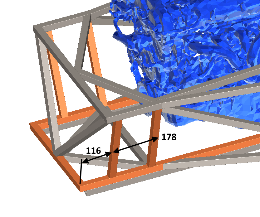
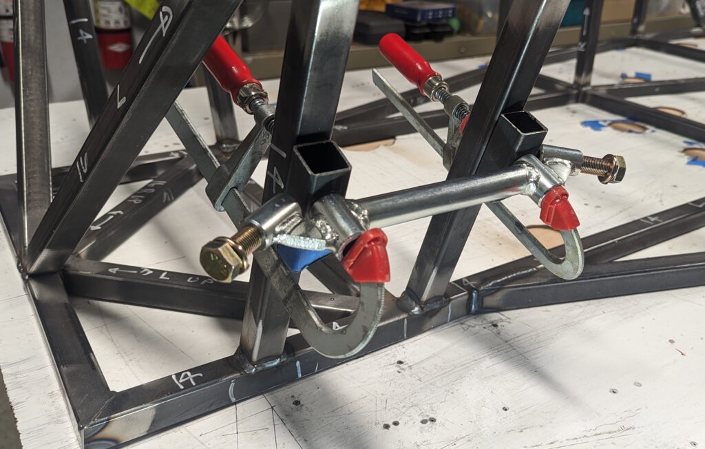
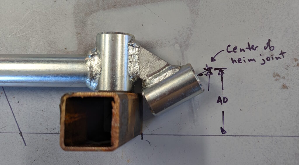
Here is my concept for using the A-arm main shaft. I think I will just weld two stubs of tubing and bolt to that (with support between the stubs), but there is the option of using the adjustable brackets as described in Sevenesque.

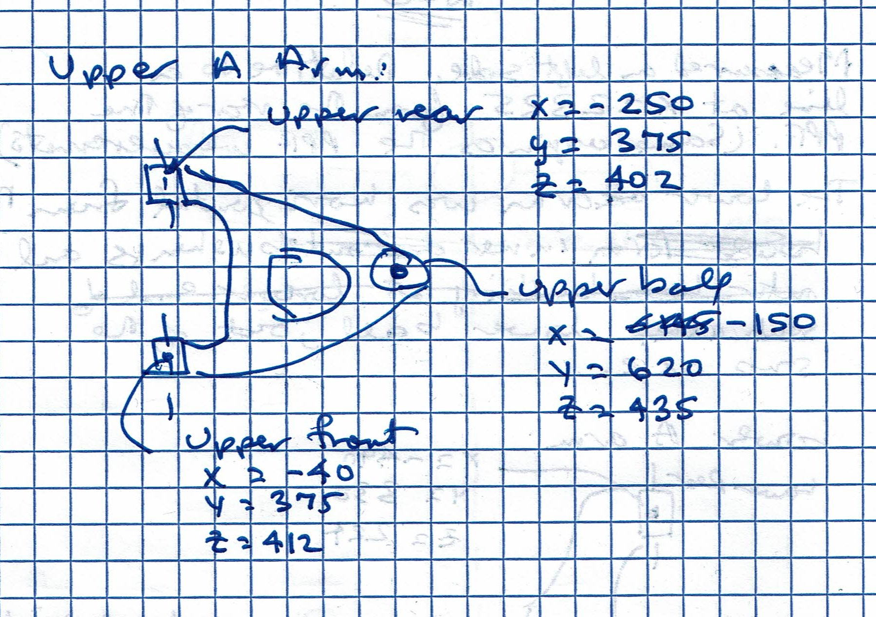
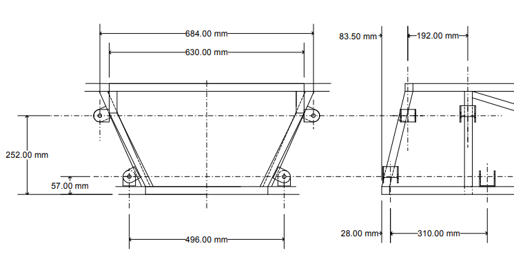
For reference, the Vodou front suspension mounting points are given below.
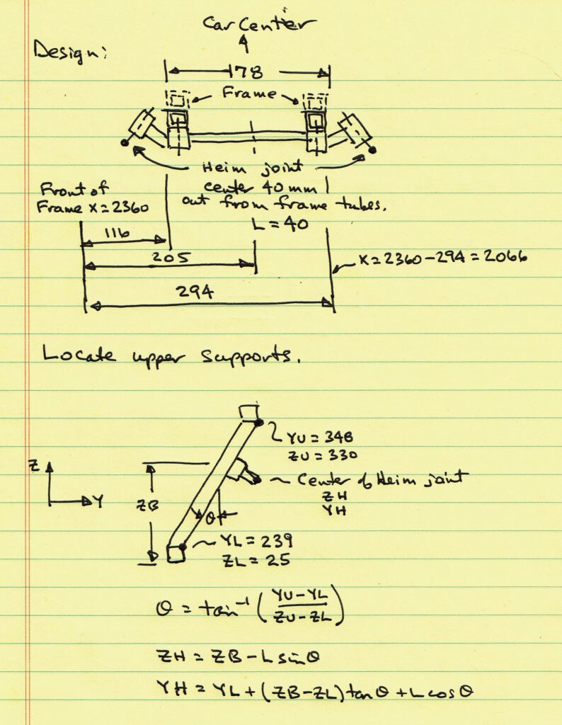
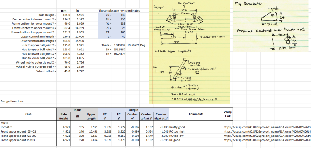
We will start by calculating the top A-arm Heim joint locations as a function of height above the bottom of the frame. We will vary the height during the roll center calculations. Here are the calculations.
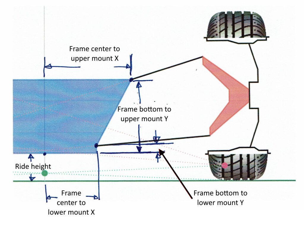
I will use VSusp to calculate roll center. This software runs in your web browser and was develop by Rob at admin@vsusp.com. It is clever in that your input data is saved in a web link, so you just save that link and you can open it later to get back to your work.
The following input data is required.
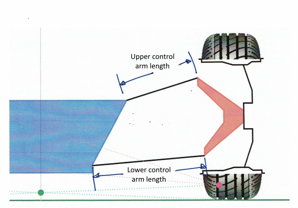
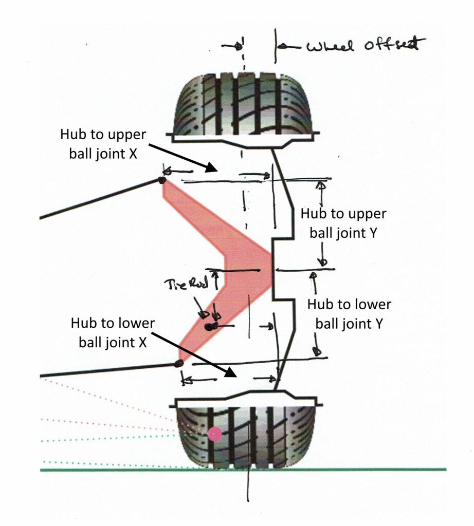
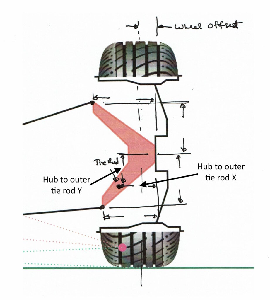
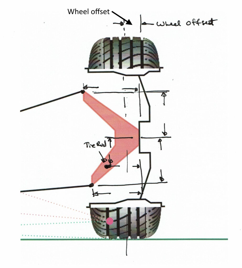
Here are my measured values for the hub and wheel. These were measured using a square and tape measure relative to the hub. You will notice a slight discrepancy for the Hub to upper ball joint X value in this figure vs. measurements from the car centerline given in the Suspension #1 post. Here I measure 125 mm and in the other measurement the value is 130 mm. I will use these numbers.
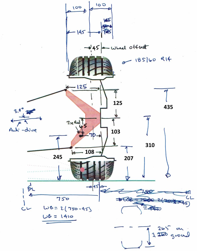
I used a spreadsheet to help calculate the VSusp input values.
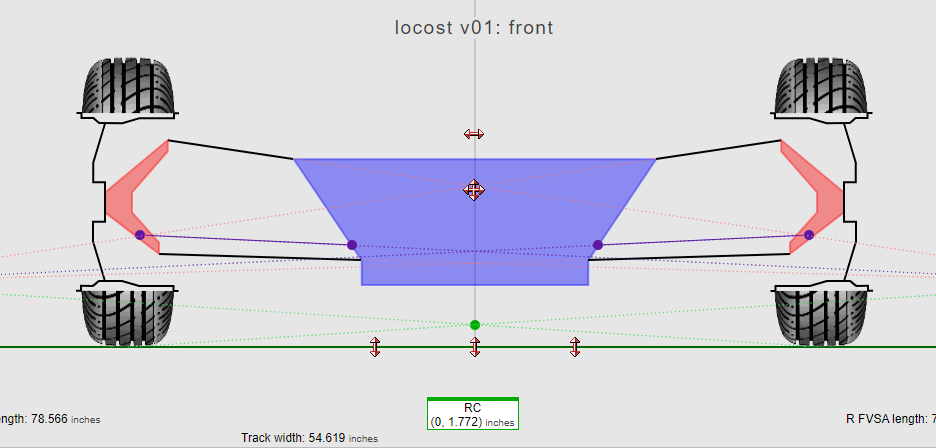
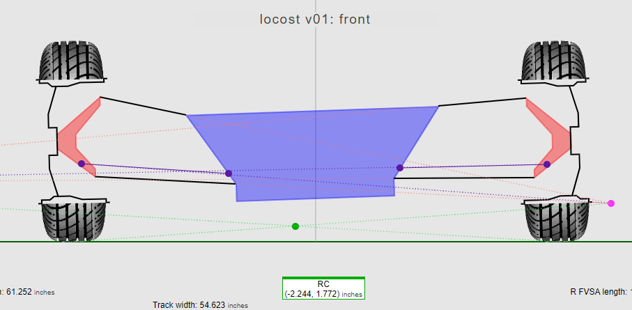
Here are figures showing the VSusp calculations for the Locost 01 case. The first is with zero roll and the second at 2 degrees of roll. Hopefully 2 degrees of roll is all I expect to see.
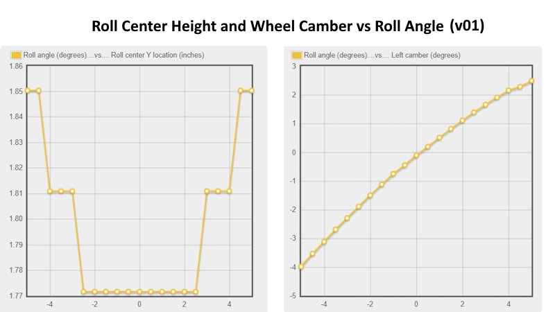
Here is a plot of roll center height and camber change on the left (outer) tire as a function of roll angle.
And here is a summary of the results. I think I like the Locost 01 case. It has a reasonable roll center height based on Staniforth and reduces the camber change with roll pretty reasonably. It is somewhat surprising how sensitive the roll center is to the location of the inner upper A-arm support. I can see some advantage to having an adjustable attachment, but the bracket is large and does not fit well on the frame. I think as long as I go for the Locost 01 case and measure carefully, things should be ok.

A couple of other things:
- The upper A-arm center is positioned 20 mm behind the lower A-arm. This corresponds to a caster of 5°. This is the same value as in the Miata.
- On the Miata the front bracket of the upper A-arm support was 10 mm mm above the back bracket. This gives some anti-dive. I will probably include in my final assembly.

