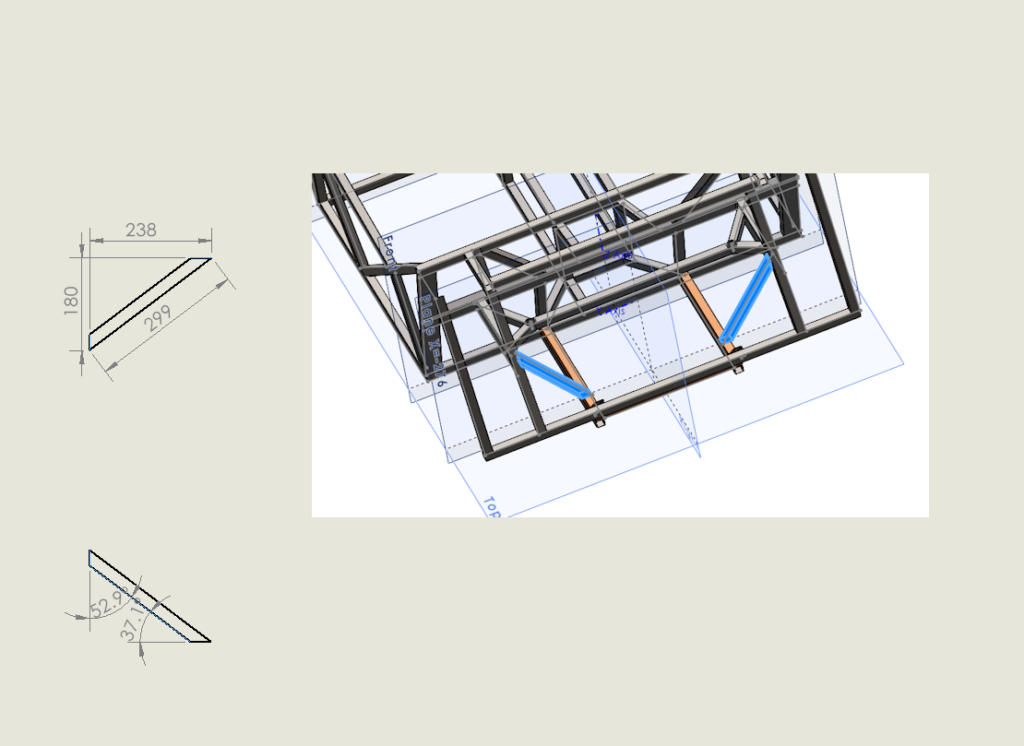
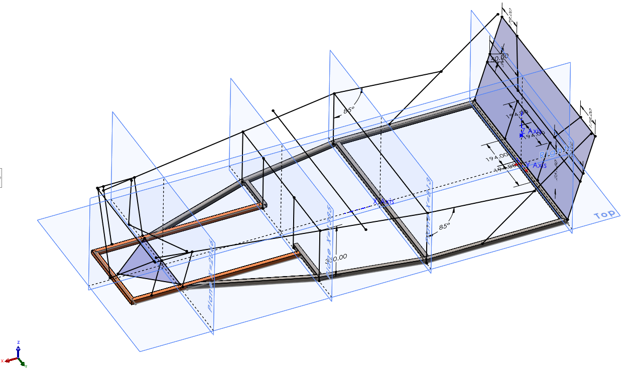
Now we will display the dimensioned drawings. Here is a file with the drawings.
You will notice I did not make part drawings of individual tubes. The results in a lot of drawings and is not how I worked. I worked in tube groups corresponding to each of the following drawings.
The Base
The base is the simplest. All you do is draw the outline on the table, cut the tubes, and weld everything together. Tack welds first, then carefully you can do some full welds but watch for distortion.
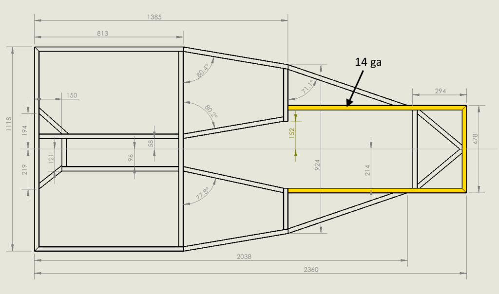
Seat Back
This just shows the dimensions of the seat back. I did not make the seat back as an assembly. See the next image.
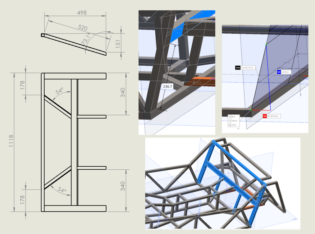
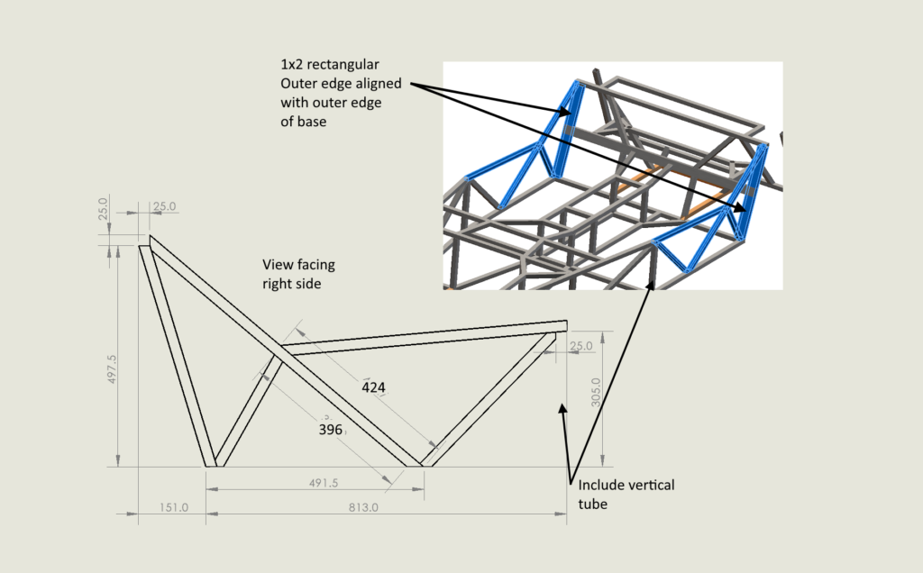
Rear Side Assemblies
I made both of these on the flat table then assembled onto the base and added the seat back cross pieces.
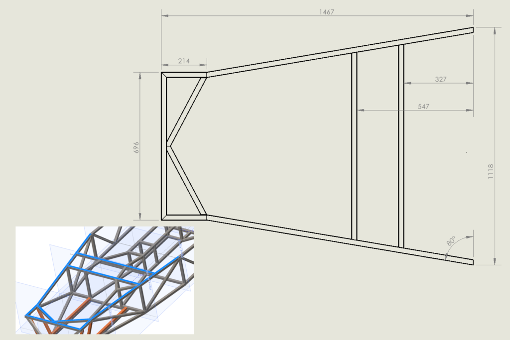
Upper Forward Assembly with Supports
I built just the front straight section with the two diagonals, then mounted that on the base, then added the long sides and cross pieces.
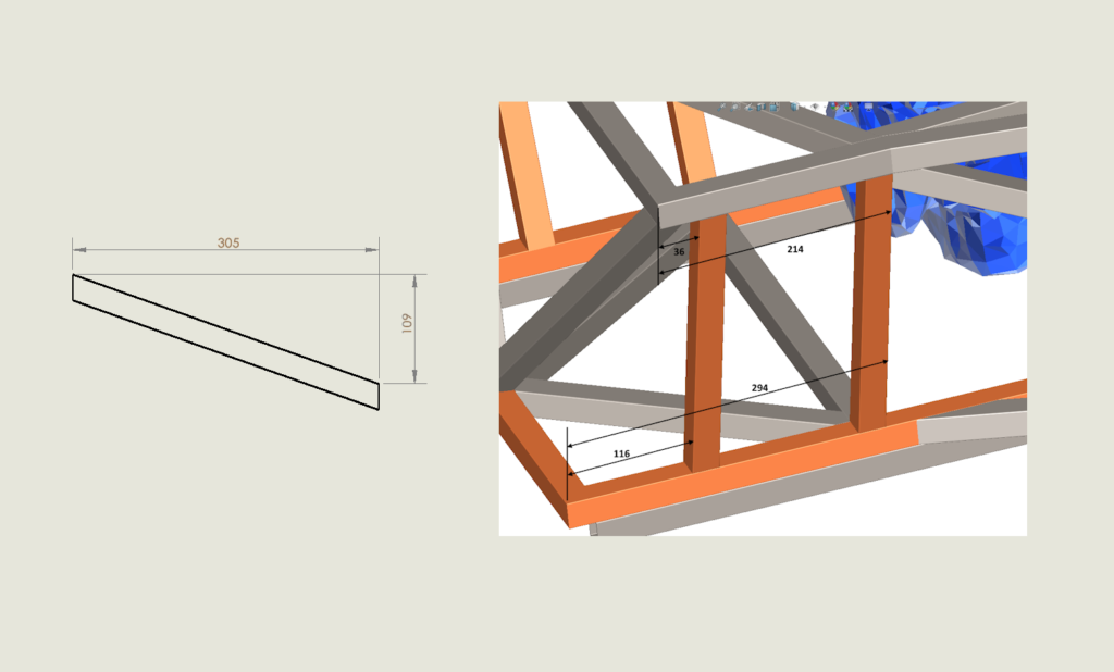
The A-Arm Supports
Used to attach the front straight section to the base.
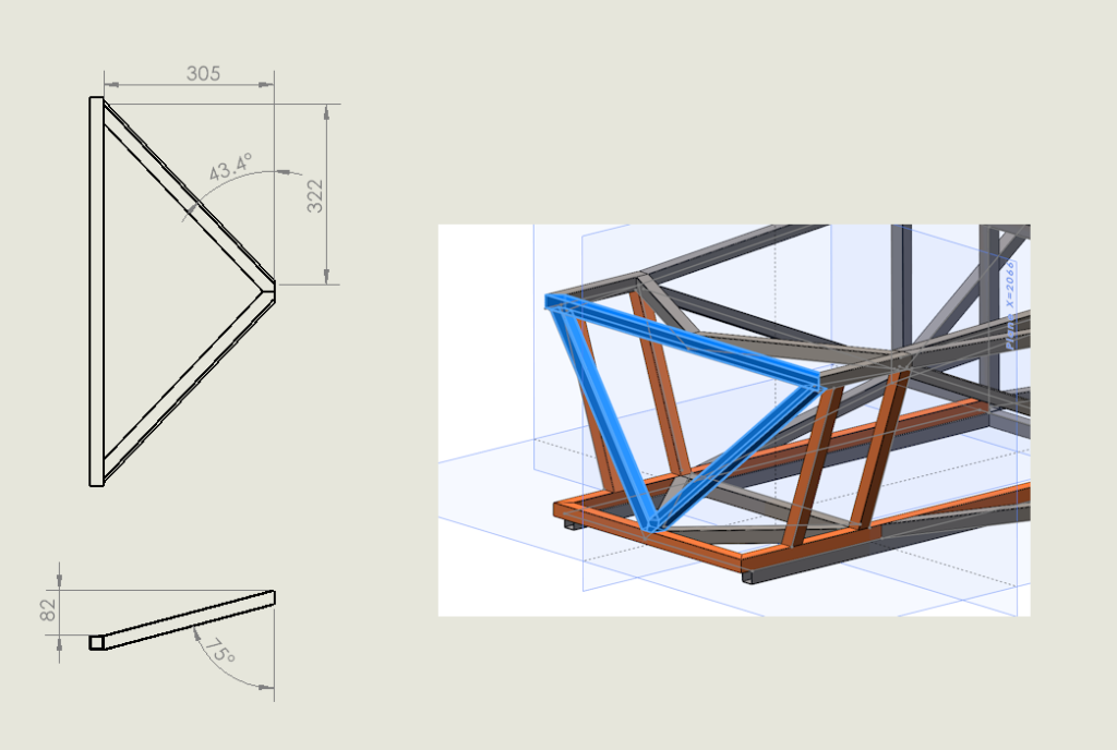
The Front Diagonals
Note that 305 mm is the vertical distance, not the true length of the tube. Hand fitted.
Driveshaft Tunnel
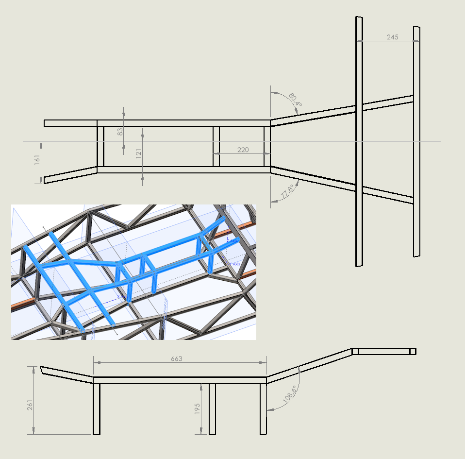
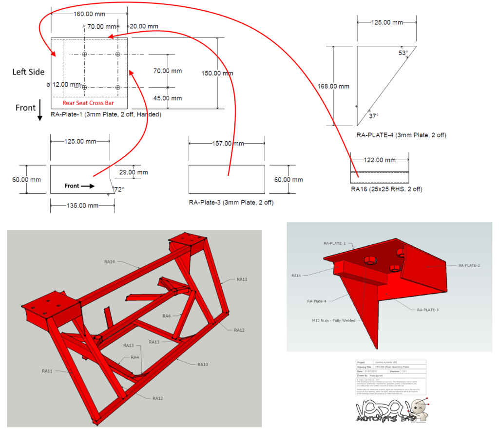
Rear Frame Assembly Plates
For some reason, this assembly was confusing to me at first. I finally got the orientation right and things made sense.
Rear Frame – Assembly #1
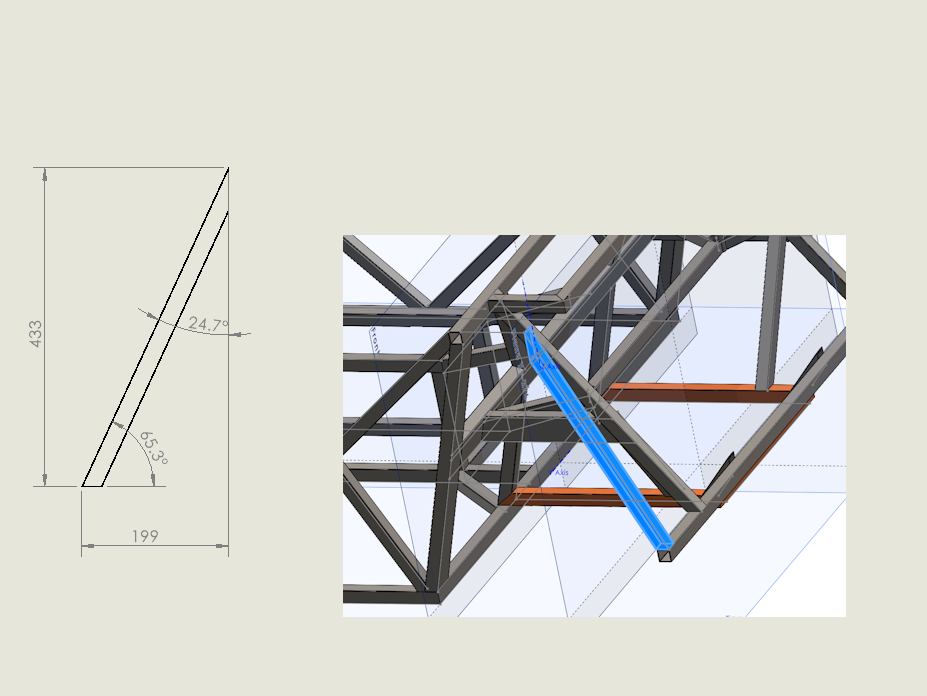
Rear Frame – Assembly #2
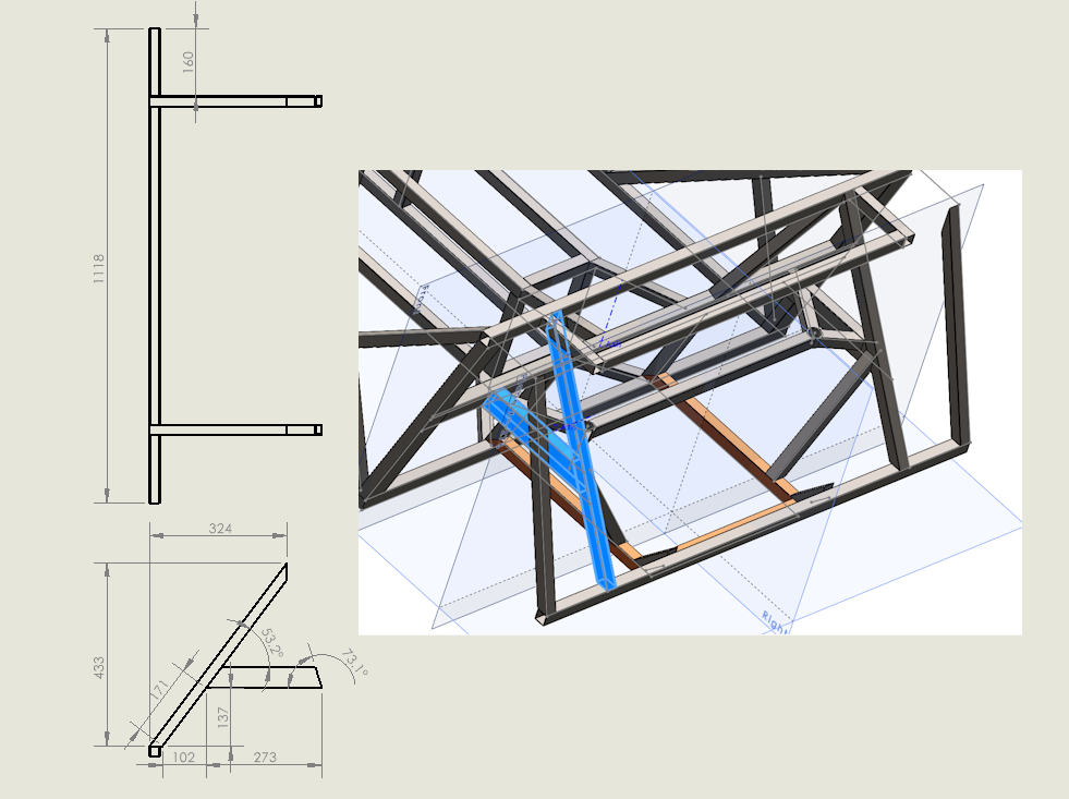
Rear Frame – Assembly #3
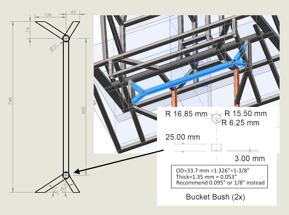
Rear Frame – Assembly #4
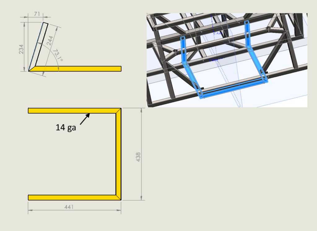
Rear Frame – Assembly #5
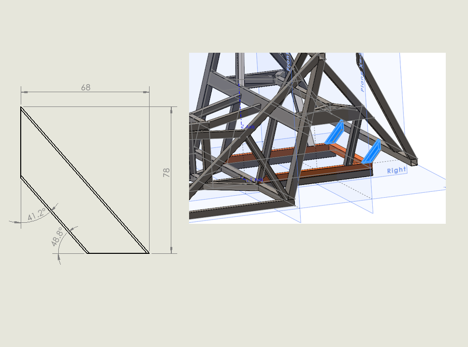
Rear Frame – Assembly #6
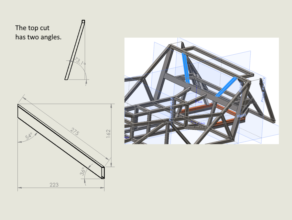
Rear Frame – Assembly #7
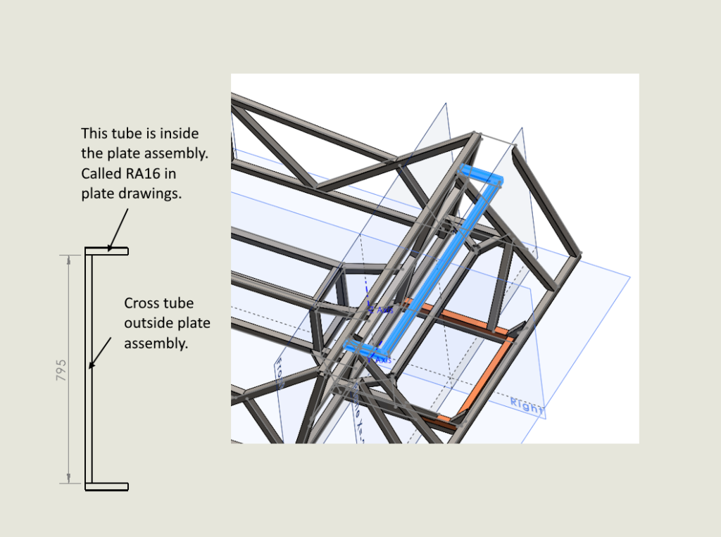
Rear Frame – Assembly #8
