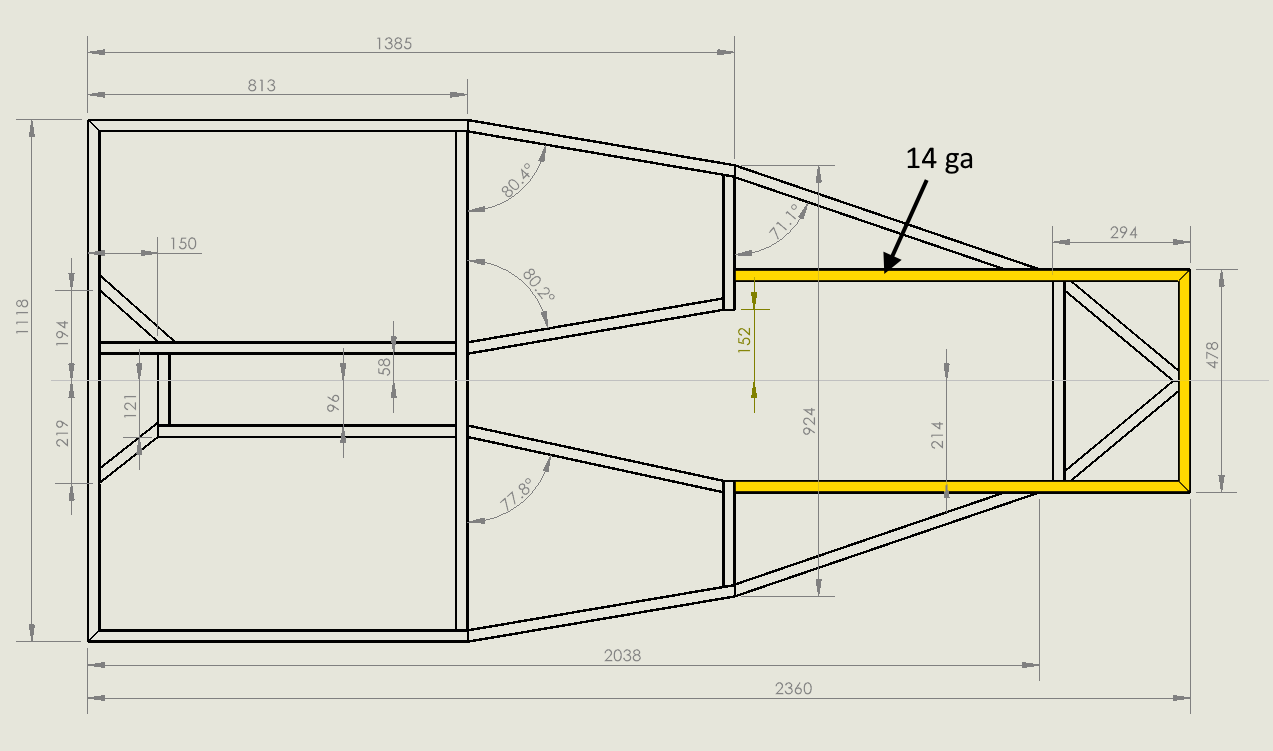
I decided to draw my design using CAD after seeing Tools-n-Track struggle with unexpected interference problems using the Vodou drawings. Also, I wanted to change the front suspension mounts and include the PPF, neither of which are included in the Vodou design.
I am using the maker edition of SolidWorks. It is inexpensive, about $100/year, and powerful. The maker version uses 3DEXPERIENCE and here is a link to some information. Unfortunately this version does not include finite element analysis capability to calculate stresses. But I can do hand calculations, trust that the Haynes design has been tested in practice, and will use some ideas from the finite element paper to compensate.
My CAD skills are basic, so don’t expect fancy drawings. I am using the weldments option of SolidWorks. You make a 3D sketch using lines, define the weldment type you want to use, and then assign those weldments to the appropriate lines. Here is a link to the most useful weldments instructions that I found. And here is a link to a SolidWorks Instructions document that includes random items that I use. SolidWorks.
Steps in Using SolidWorks
There are several steps in using SolidWorks. First you make a 3D sketch that defines points and lines. The lines will be turned into weldments. Your part can include multiple sketches. In the image below I have already completed a base sketch and added weldments to that sketch. Now I am working on the “middle” sketch.
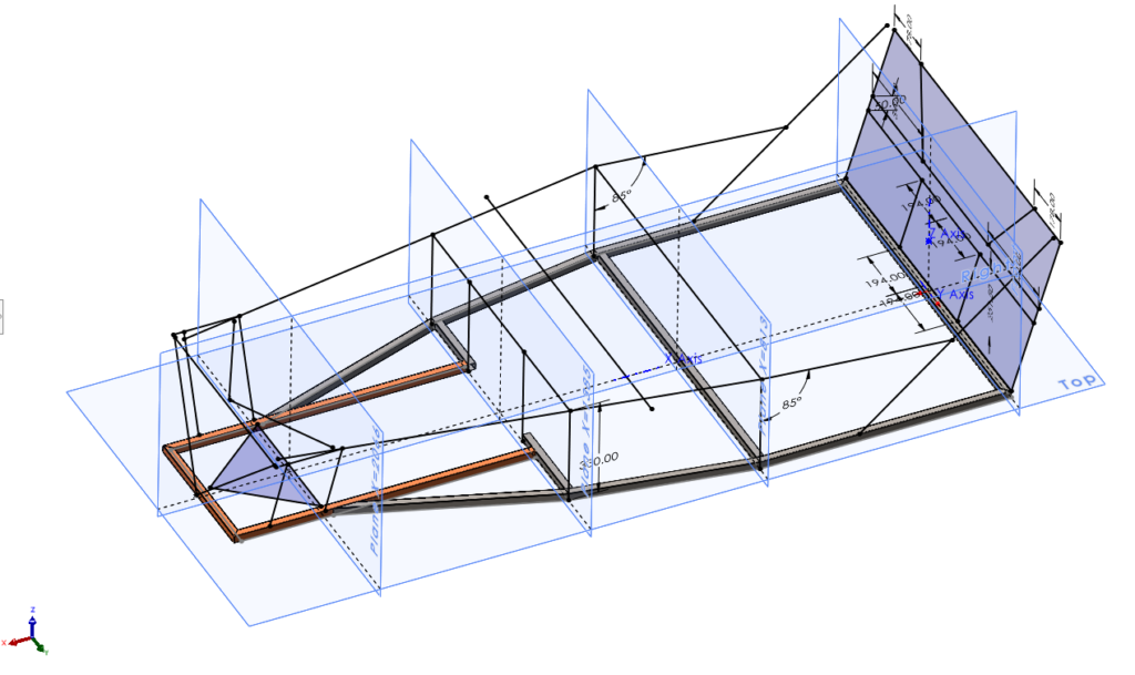
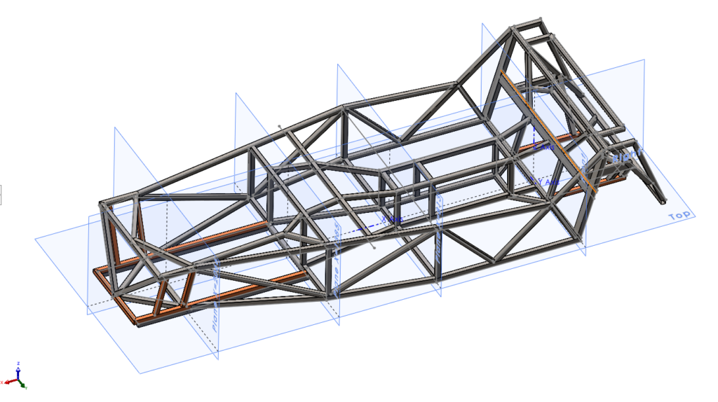
The final part drawing uses multiple sketches. Here is the current status of the frame (2023-12-01). Note that I have not drawn any of the plates that strengthen the rear assembly and support the rollbar.
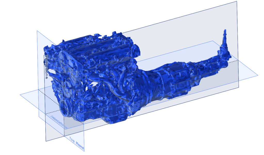
I was fortunate to find point cloud images (.rcs files) of the engine and differential on the LocostUSA forum. Then I processed the point cloud images using the Autodesk ReCap Pro software to convert the .rcs files to .pts files. I used MeshLab to read the .pts files and triangulate the points and write .stl files. I could then import the .stl files into SolidWorks. Here are some links:
- A pdf file I wrote with the links to the web instructions and how to use Autodesk ReCap Pro and MeshLab.
- The stl files I imported into SolidWorks.
After that work, here is how the engine displayed in SolidWorks.
And here is the assembly as of 2021-12-01 that shows everything together.
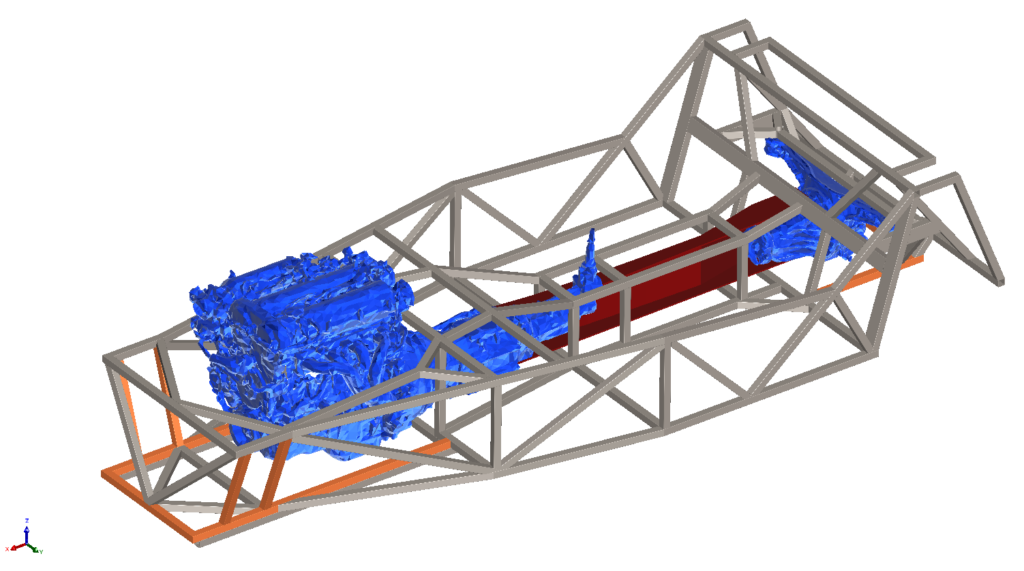
The whole point of the exercise is to identify any interference problems and change the design to avoid them. Spinning the model helps and so does looking at top, side, and front views. You can see that a small bulge will be needed to clear the transmission on the driver’s side. Keith Tanner had the same problem with his kit car.
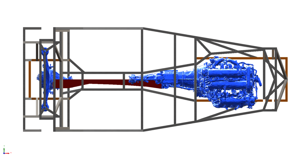
Hopefully, when I test assembly the engine and differential in the frame, everything will fit.
