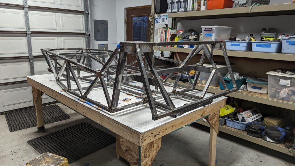
Building the frame is the most straight-forward part of the build. You measure, cut, and weld. My guess is that when the frame is finished, you have completed about 25% of the work. There are a lot of other tasks ahead.
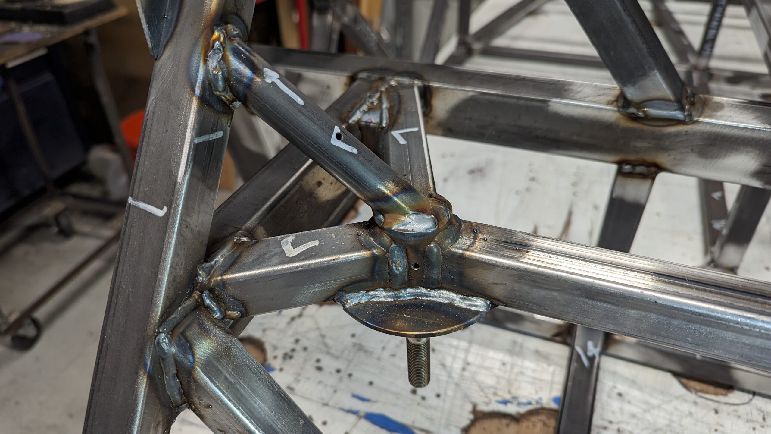
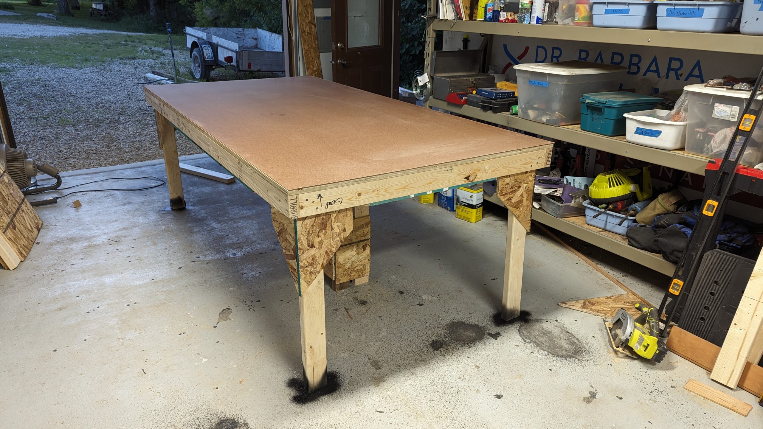
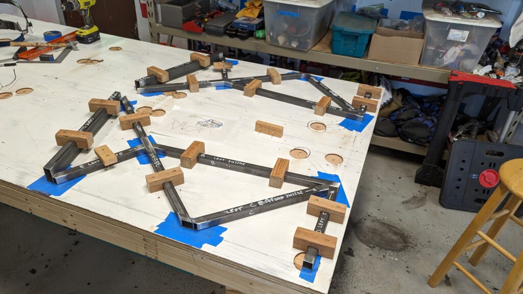
I built this in assemblies, drawing each assembly on the table. The thin sheet of painted fiberboard on the table makes this easy. Then I cut holes at the weld locations. That stops the table from burning. It also makes it possible to flip the assembly over and weld the opposite side without grinding the welds flat.
So this is the base. I used two clamps on each tube when actually doing the welding.
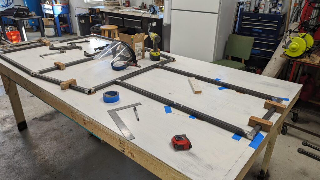
Here I am welding the side assemblies.
The side assemblies and part of the rear seat support tack welded to the base.
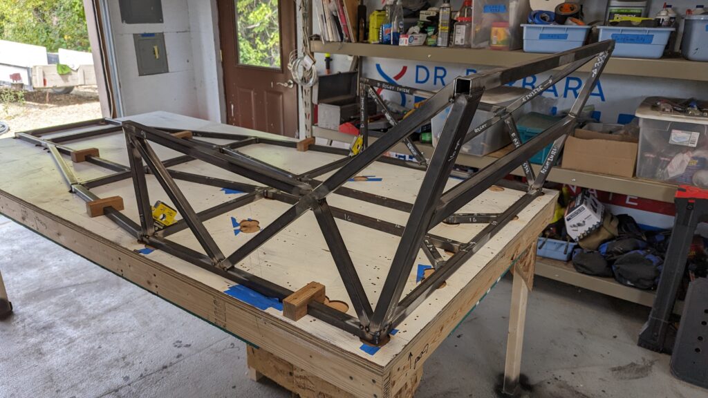
Working on the front assembly. Really trying to be precise here.
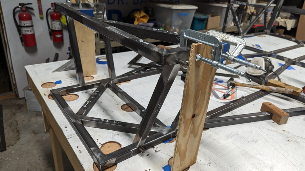
Early morning in the shop!
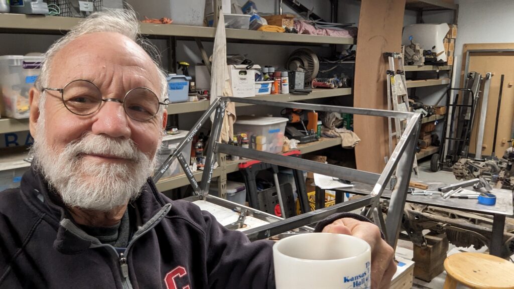
The driveshaft tunnel. It took me three tries to get that compound angle on the right tube correct. It was easier after I figured out that I could cut compound angles on the bandsaw. When I started, I cut one angle on the band saw and then used the flat grinder to make the second angle.
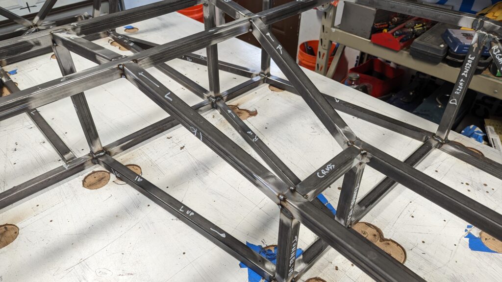
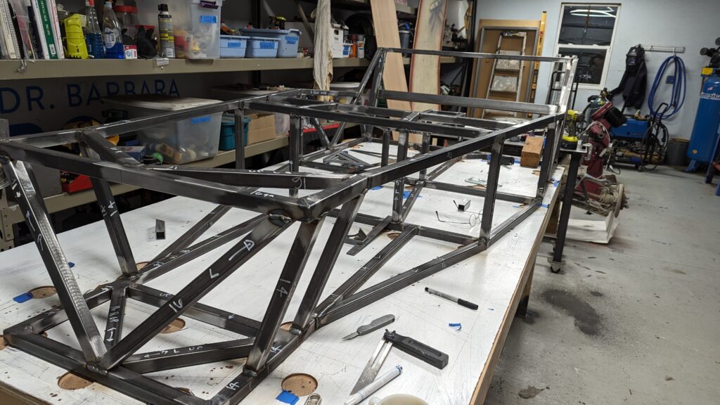
Things coming together. Now need to do the rear suspension support.
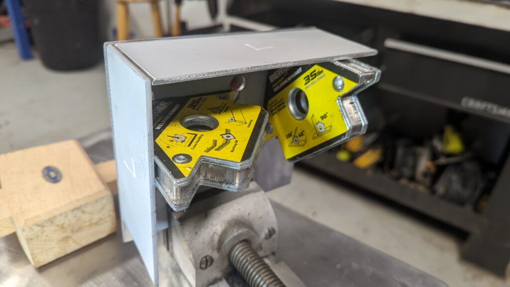
Starting to weld the rear assembly plates. First fit the pieces together. (2023-12-21)
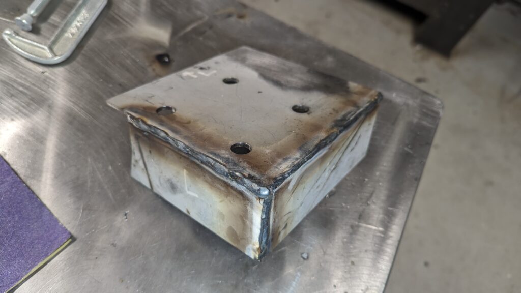
Then welded. Not real pretty, but sturdy for sure. Welds on inside and outside. (2023-12-21)
The rear assembly plates tack-welded in place. View from the left. I clamped the plate assembly in position, then tack-welded the diagonal brace. I then removed the assemble and welded the diagonal brace on both sides so that I would have a complete circumferential weld attaching the diagonal to the top set crossbar.
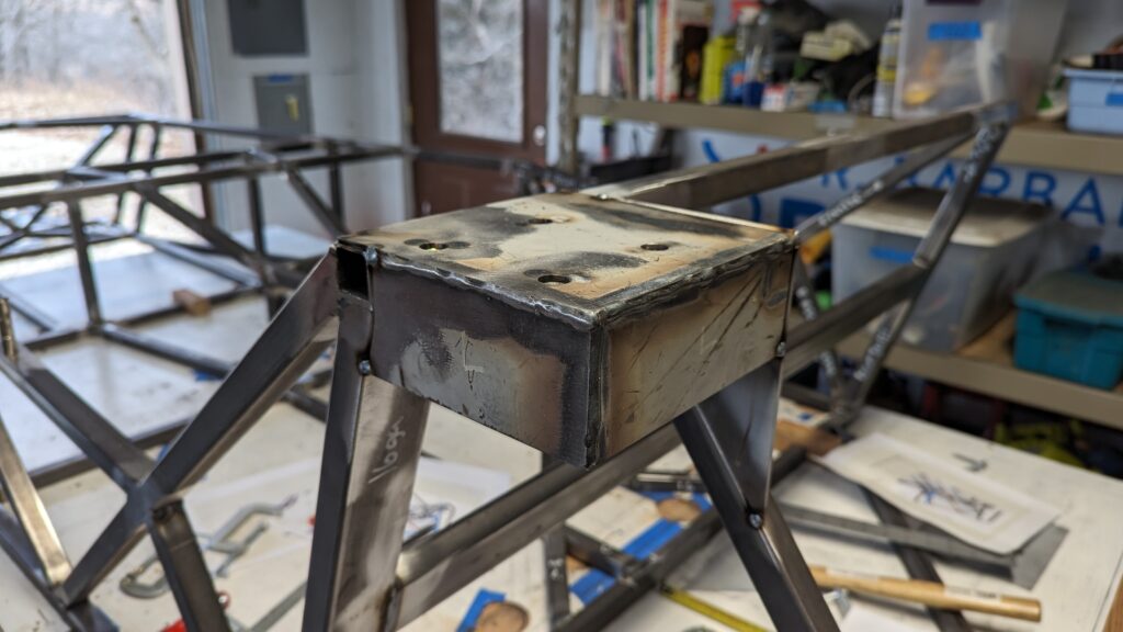
View from the right side.
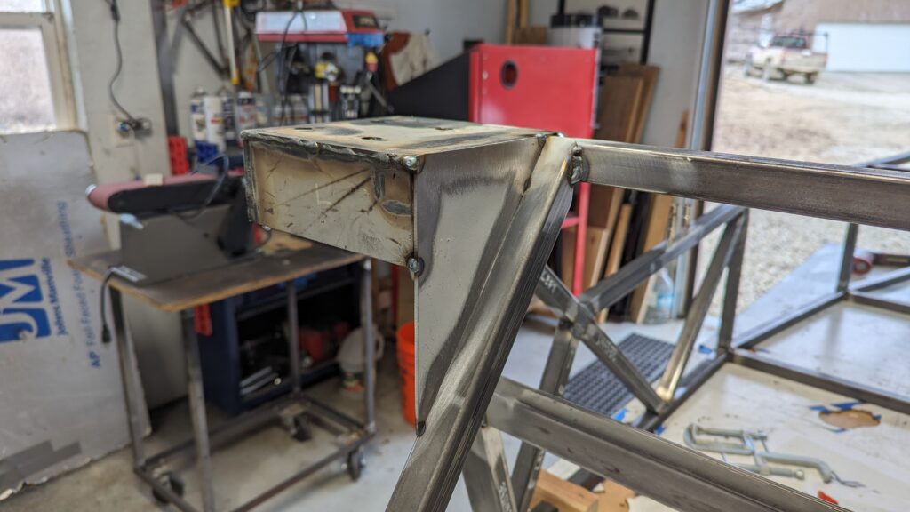
And from underneath looking from left to right.
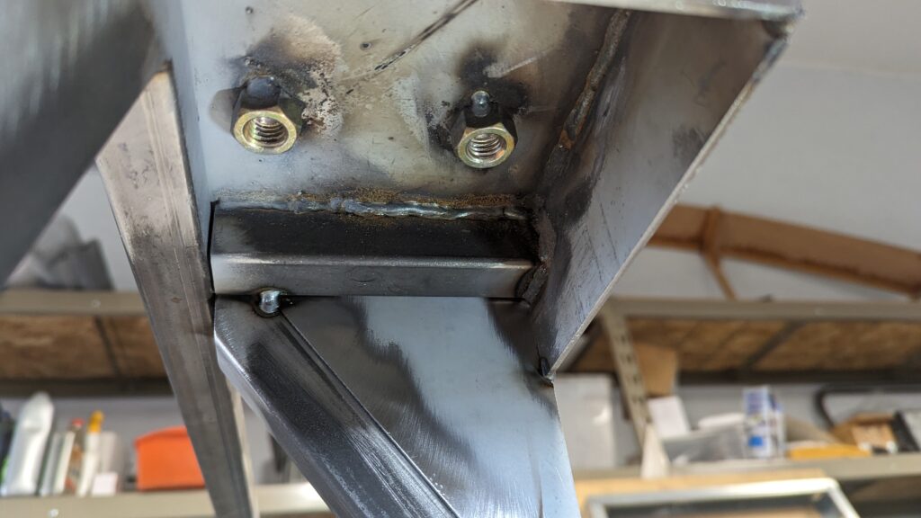
Both plate assemblies tack-welded in place with both diagonal braces to the lower rear crosstube. (2023-12-22)
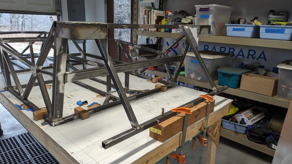
Continued adding tubes to the frame.
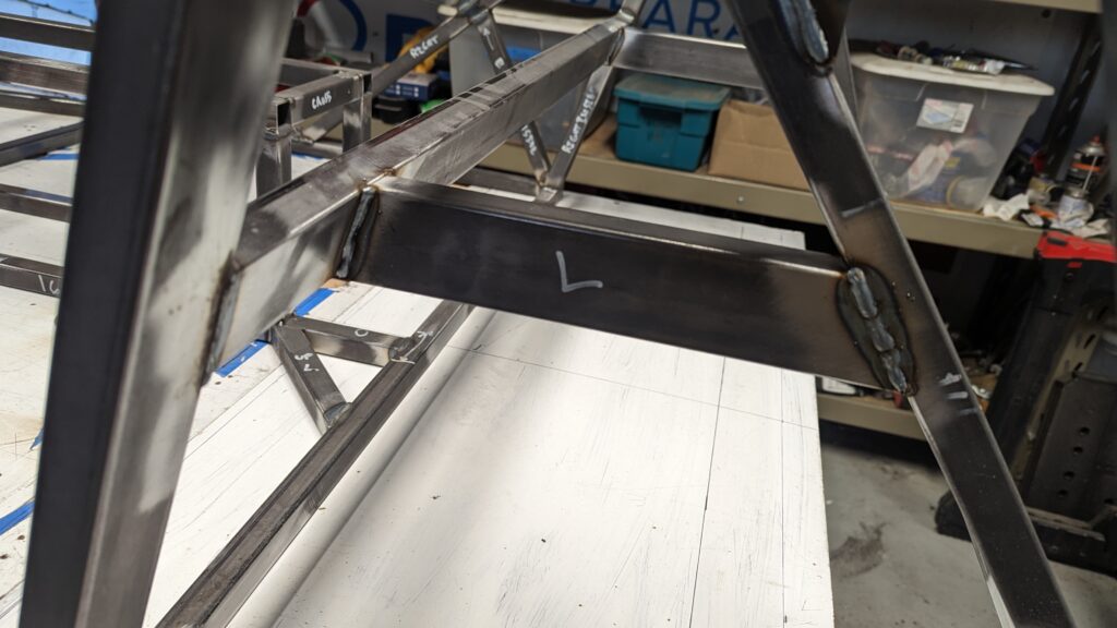
Now the lower rear tubes.
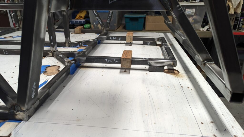
Based on a simple beam stress calculation, the front tube that supports the engine had marginal strength. I made two changes. First, I used 14 gauge tube for the main tube. Then I added a 16 gauge tube below the main tube. By deepening the beam, the moment of inertia is increased and adds a lot of strength. You can see I also used 14 gauge tube for the vertical suspension supports. This idea came from the LocostUSA forum as a “lesson learned” by one builder.
The second benefit of this bottom tube is to protect the engine sump. It also opens up alternative options for the lower front suspension attachments.
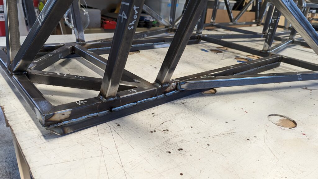
Similarly, I added a second lower tube at the rear. Here the two reasons are for more strength, but also to make a strong mount for the rear suspension attachments. Note that to set the frame level I need to support it 25 mm above the table. As for the front, the primary lower tubes are 14 gauge.
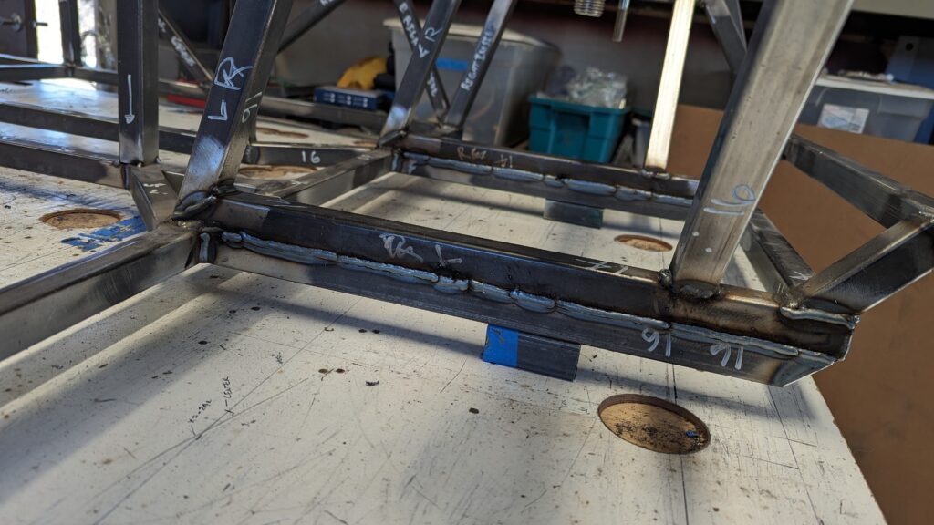
I also added the side diagonals, finished the rear tubes, and fully welded all the joints except for the tunnel. The last major part of the frame is the differential support which deserves its own post.
